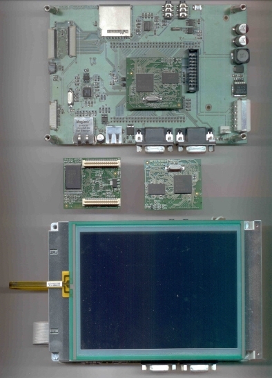
 RD126
RD126
Development board for RD129 CPU

To power the board only 5Vdc is required. Full schematic is included with the board.
The board contains:
- 3.3V switching power supply
- Level translator for 2 RS232 serial interfaces
- USB to Ethernet converter, and its connector
- USB Host connector
- MMC or SD flash memory card connector
- 16 bits in/out stereo audio codec
- IICbus eeprom
- Real Time Clock whith litium back-up coin battery
- FPC connectors for optional LCDs
- JTAG debug connector
- One RD129 CPU board
Can be optionally provided with one of these LCD displays:
- TFT 3.5" 240x320 LED backlighted
- STN 5.7" 320x240 CCFL backlighted and its inverter
- TFT 5.7" 320x240 CCFL backlighted and its inverter

